China’s rapidly growing construction sector has made steel a central material for high-rise buildings, factories, bridges, and public infrastructure. Yet steel alone does not guarantee safety. Engineers must control load paths, connection behavior, buckling risks, corrosion exposure, and construction tolerances. This article introduces how to improve structural stability with steel through practical design and site-based decisions.
Fazlur Rahman Khan, a pioneering structural engineer, once said, “Technical men must think technically, but their technicality must be tempered with an appreciation of the human element.” His words remain highly relevant to steel construction. A stable frame must resist gravity, wind, earthquakes, vibration, and accidental imperfections. Engineers can improve performance by selecting suitable steel grades, using braced or moment-resisting systems, and designing connections for real forces rather than ideal assumptions. Bolts should be properly tightened. Welds require qualified procedures and reliable inspection. Small errors can become serious weaknesses.
Steel is not magic.
In practice, stability also depends on fabrication, transportation, erection sequence, and maintenance. A well-designed column can still buckle when temporary bracing is removed too early. A protected beam can still lose capacity when coatings deteriorate unnoticed. Chinese projects should follow applicable standards, including GB 50017, while verifying local wind, seismic, and environmental conditions. Digital modeling can expose hidden weaknesses, but it cannot replace experienced engineering judgment. That is the uncomfortable part. Calculations may appear precise, while site conditions remain uncertain. Therefore, improving stability requires cooperation between designers, fabricators, inspectors, contractors, and owners. The strongest solution is not always the heaviest one. It is the one that remains dependable when materials, workers, weather, and assumptions differ from the original plan.
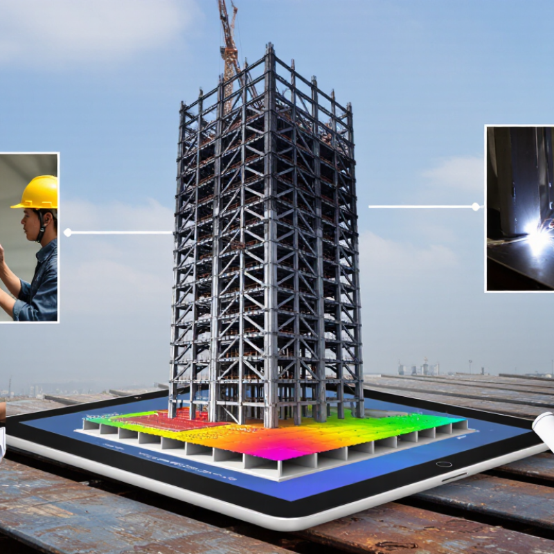
Structural stability depends on how steel carries force, not simply on its strength. Steel offers high tensile capacity and predictable stiffness. This allows slender beams, columns, and braced frames. However, slender members may buckle suddenly under compression. Effective length, end restraint, and imperfections matter greatly. AISC 360-22 requires engineers to consider second-order effects and member instability. These checks reveal a practical truth: small alignment errors can change a perfect calculation.
A stable steel frame needs continuous load paths. Forces should travel from floors to beams, columns, foundations, and soil. Connections deserve equal attention. Loose bolts, weak welds, or flexible joints can reduce system stiffness. Corrosion and fire exposure also weaken steel’s resistance. The World Steel Association reported 1.892 billion tonnes of crude steel production in 2023. That enormous volume makes consistent inspection essential, especially for structural grades and connection materials. Still, data cannot replace judgment. A spreadsheet may be exact while the building is not.
Tips: Use lateral bracing early in the design. Check buckling in both directions. Review connection stiffness, not only strength. Inspect column alignment on site. Protect exposed steel from moisture and fire. Recheck assumptions when construction differs from drawings.
Steel stability starts with grade selection, not simply thicker members. Engineers should define loads, span, temperature, corrosion exposure, and connection details. Yield strength controls resistance, while toughness limits brittle failure during impact or low temperatures.
The 2024 World Steel in Figures report records 1,888.2 million tonnes of crude steel production in 2023. That scale highlights a practical issue: availability does not guarantee suitability. A common mistake is choosing a grade before reviewing weldability.
For ordinary building frames, grades near 355 MPa yield strength often balance strength and fabrication performance. Higher-strength grades may reduce member weight, but they can increase welding controls and buckling sensitivity. GB/T 1591 and Eurocode 3 both support checking strength, toughness, and fabrication conditions.
Seismic projects need certified impact toughness and ductility. Request mill certificates, heat numbers, Charpy results, and dimensional tolerances. Traceability matters.
Site experience often reveals overlooked details. A beam may pass calculations yet lose capacity through poor fit-up, residual stress, or corrosion. The American Institute of Steel Construction Specification 360-22 treats material properties, connections, and fabrication quality as linked requirements.
I have seen teams select the strongest available steel too early. That decision looked efficient. It was not always efficient. Review welding qualifications, fire protection, life-cycle cost, and future inspection access before approving the grade.
China Top How to Improve Structural Stability with Steel?
Designing Efficient Steel Connections and Load Paths
Structural stability begins where members meet. A beam may look oversized, yet a weak joint can govern the entire frame. Engineers should define continuous load paths from slabs and beams to columns, foundations, and the ground. Each transfer deserves a clear force diagram.
Bolted end-plate connections need adequate bolt pretension, edge distances, and plate thickness. Welded joints require controlled heat input, access for inspection, and realistic erection tolerances. The 2022 Specification for Structural Steel Buildings emphasizes strength, stability, and connection detailing through limit-state design. In practice, tiny gaps at a column base can change bearing behavior. That detail is easy to underestimate.
Load paths should also resist accidental local damage. Redundant beams, tied floors, and alternate vertical routes can limit progressive failure. The National Institute of Standards and Technology has repeatedly highlighted connection behavior and construction quality in structural failure investigations. The 2024 World Steel in Figures report recorded about 1.89 billion tonnes of crude steel production in 2023, showing the material’s global importance. Quantity, however, does not guarantee reliability. A competent design team checks fabrication drawings, bolt installation, weld records, and site observations. Digital analysis helps, but models may hide poor assumptions. I still question every “perfect” connection detail when field tolerances are unknown.
| Design Dimension | Connection or Stability Element | Load Path and Structural Function | Key Design Data or Requirement | Primary Verification Checks | Applicable Reference |
|---|---|---|---|---|---|
| Material selection | Structural steel members and connection components | Transfers tension, compression, shear, bending moment, and torsion through a continuous steel framework. | Q235 steel has a nominal yield strength of 235 MPa for the applicable thin-plate range; Q355 steel has a nominal yield strength of 355 MPa for the applicable thin-plate range. Actual design values depend on thickness, product standard, and design code. | Yielding, rupture, local buckling, corrosion allowance, weldability, and compatibility between connected components. | GB/T 700; GB/T 1591; GB 50017 |
| Global load path | Beam-to-column framing system | Floor and roof loads move from slabs or decking to beams, then to columns, foundations, and finally the ground. | Every change in force direction should have a clearly defined transfer mechanism. Avoid unsupported force discontinuities and eccentric load introduction. | Equilibrium, member strength, connection stiffness, frame drift, second-order effects, and robustness under local damage. | GB 50017; GB 50009 |
| Shear transfer | Bolted shear connection with a fin plate or angle cleat | Beam web shear flows through bolts into the connection plate and then into the supporting column or girder. | Use adequate bolt rows, edge distances, pitch, plate thickness, and bearing area. The connection should permit practical erection tolerances without unintended restraint. | Bolt shear, bolt bearing, plate bearing, net-section rupture, block shear, weld strength, and supporting-member local failure. | GB 50017; JGJ 82 |
| Moment transfer | Bolted end-plate moment connection | Beam tension and compression forces form a couple. Bolts and end plates transfer tension while the compression zone bears against the supporting member. | The lever arm between tension and compression resultants strongly influences moment resistance. End-plate thickness and bolt-row arrangement govern stiffness and prying action. | Panel-zone shear, bolt tension, bolt prying, end-plate bending, weld strength, column flange bending, and rotational stiffness. | GB 50017; JGJ 82 |
| High-strength bolting | Preloaded slip-resistant bolted connection | Transfers shear through friction between faying surfaces, reducing slip under service loading when the joint is properly preloaded. | Property class 8.8 bolts have a nominal ultimate tensile strength of 800 MPa and a nominal yield strength of 640 MPa. Required pretension and installation control must follow the selected standard. | Slip resistance, bolt tension, bolt shear, combined actions, faying-surface condition, pretension verification, and hole geometry. | GB/T 3098.1; GB 50017; JGJ 82 |
| Welded load transfer | Fillet-welded or full-penetration groove-welded joint | Welds transfer force directly between connected steel elements through the weld throat or complete fusion zone. | For a fillet weld, the effective throat is approximately 0.7 times the nominal leg size for a standard 90-degree fillet weld. Minimum weld size depends on the thicker connected part and the applicable code. | Effective throat strength, electrode or filler-metal compatibility, heat-affected-zone behavior, weld defects, fatigue, lamellar tearing, and distortion. | GB 50017; GB/T 985.1; GB/T 11345 |
| Compression continuity | Column splice with bearing plates or flange-web continuity details | Transfers axial compression through direct bearing and transfers bending and shear through plates, bolts, or welds. | Bearing surfaces should be prepared and aligned so that compression is not transferred through unintended gaps, thin cover plates, or localized contact points. | Contact pressure, plate bending, bolt tension, weld strength, column alignment, local buckling, and cumulative construction tolerances. | GB 50017; JGJ 82 |
| Bracing system | Concentric bracing with gusset plates | Transfers lateral wind or seismic forces through braces into beams, columns, diaphragms, foundations, and the ground. | Brace members should be arranged to provide a stable triangulated load path. Gusset plates require sufficient clearance for brace rotation and expected inelastic deformation where applicable. | Brace tension and compression, slenderness, gusset yielding, Whitmore-section strength, bolt or weld resistance, and out-of-plane buckling. | GB 50017; GB 50011 |
| Floor diaphragm action | Steel deck, concrete slab, and collector connection | Distributes horizontal loads to braced frames, moment frames, or shear walls through diaphragm shear and collector forces. | Deck sidelap fasteners, deck-to-support attachments, slab reinforcement, collectors, and chord members must be designed as one continuous horizontal load path. | Diaphragm shear, collector tension and compression, fastener failure, deck buckling, interface slip, and opening reinforcement. | GB 50017; GB 50010; GB 50011 |
| Base connection | Column base plate with anchor rods | Transfers axial force, shear, and overturning moment from the steel column into grout, concrete, reinforcement, and the foundation. | Base plates should provide adequate compression bearing area. Anchor rods primarily resist uplift and shear where friction or shear keys are insufficient. | Concrete bearing, base-plate bending, anchor-rod tension and shear, pull-out, breakout, pry-out, weld strength, and grout compression. | GB 50017; GB 50010; JGJ 145 |
| Member stability | Lateral restraints, bridging, and intermediate bracing | Restrains lateral or torsional movement of beams and compression members, allowing the intended load-carrying mode to develop. | Restraint locations and stiffness must be coordinated with the member’s unbraced length, compression flange behavior, construction stage, and loading pattern. | Flexural buckling, lateral-torsional buckling, torsional buckling, restraint force, connection stiffness, and temporary erection stability. | GB 50017 |
| Serviceability performance | Rigid, semi-rigid, or nominally pinned connection | Controls how forces and deformations are shared between connected members under service loads. | Connection classification should match the structural analysis model. Excessive flexibility can increase drift, vibration, secondary moments, and nonstructural damage. | Deflection, story drift, rotation capacity, vibration, bolt slip, fatigue, weld cracking, and compatibility with cladding or finishes. | GB 50017; GB 50009 |
| Robustness and redundancy | Continuity ties, alternate load paths, and ductile detailing | Redistributes forces when a local component is damaged, reducing the risk of disproportionate progressive collapse. | Provide dependable horizontal and vertical ties, avoid brittle failure modes, and ensure that critical connections can develop the required deformation and force redistribution. | Connection ductility, tie resistance, alternate-path analysis, disproportionate-collapse risk, local damage scenarios, and fire-related strength reduction. | GB 50017; GB 50016; applicable project robustness requirements |
| Construction-stage stability | Temporary bracing, erection bolts, and staged connection completion | Maintains stability before slabs, permanent bracing, diaphragms, and final welds or bolts become effective. | The partially erected structure must be checked separately because the final load path may not yet exist. Temporary supports should remain until permanent stability systems are complete. | Wind during erection, unbraced length, temporary connection capacity, lifting effects, column plumbness, and stability during bolt tightening or welding. | GB 50017; JGJ 82; project erection method statement |
| Inspection and quality control | Bolted and welded connection acceptance | Confirms that the installed joint can deliver the design load path and the specified strength, stiffness, and durability. | Verify material certificates, bolt grade, hole size, pretension, weld procedure, welder qualification, weld appearance, dimensional tolerances, and coating condition. | Torque or tension verification, visual weld inspection, nondestructive testing where specified, bolt installation records, and corrective-action tracking. | GB 50205; GB/T 11345; project quality plan |
Steel stability begins with a clear load path from the roof to the foundation. Engineers check compression members for local and global buckling before selecting sections. A slender column may look adequate on paper, yet small imperfections can reduce its real capacity. Bracing, stiffened connections, and shorter unbraced lengths usually improve resistance.
Deflection needs equal attention during daily use. Excessive floor movement can crack finishes, shake equipment, or make occupants uncomfortable. Designers control span, section stiffness, and connection behavior under service loads. A practical site check measures floor vibration near busy equipment and records movement at different load levels. This evidence often reveals assumptions that calculations miss.
Structural movement also comes from temperature changes, wind, settlement, and construction tolerances. Expansion joints and sliding connections can release unwanted restraint when detailed correctly. Welding sequence matters too. Uneven heating may pull a frame out of alignment before the building is occupied. Engineers should inspect bolt pretension, brace installation, and column plumbness during erection.
A perfect model does not exist. Real steel contains small bends, residual stress, and uncertain boundary conditions. That is why independent design review and regular inspections remain valuable. Digital analysis helps, but field measurements deserve serious weight. Sometimes, adding steel is not the best answer. Improving the load path may provide greater stability with less material.
Steel stability depends on controlled quality and disciplined maintenance, not material strength alone. Mill certificates should match heat numbers, grade, thickness, and delivery records. Welds require qualified procedures, trained inspectors, and suitable non-destructive testing. Field teams should also check bolt pretension, joint alignment, and connection slippage before closing inspections. Small errors can grow.
Steel stability depends on controlled quality and disciplined maintenance.
The NACE IMPACT study estimated that global corrosion costs reach about US$2.5 trillion annually, equal to approximately 3.4% of global GDP. This figure shows why protective coatings, drainage, and corrosion monitoring deserve early attention. Coating thickness should be measured after application, while damaged areas need prompt repair.
A 2023 industry review by the International Organization for Standardization also reinforces documented quality processes through ISO 9001 principles, including traceability, corrective action, and continual improvement. Yet paperwork alone cannot prove stability. Some inspection records remain too general, which is a weakness worth correcting.
Tips:
Photograph concealed connections before access closes. Mark inspection dates on structural drawings. Check rust near weld toes, bolt holes, and water traps after heavy rain. Record torque readings, coating thickness, and visible deformation. Use risk-based inspection intervals, but review them after unusual vibration, impact, or severe weather. When uncertain, obtain an independent structural assessment.
Review loads, spans, temperatures, corrosion exposure, and connection details. Yield strength resists loads. Toughness reduces brittle failure risks. Do not choose the thickest or strongest steel automatically.
No. It may reduce member weight but increase welding controls and buckling sensitivity. A moderate grade can perform better overall. Cost and fabrication matter too.
Poor weldability can create defects, distortion, and residual stress. Review welding procedures before approving the material. Strength alone is not enough.
Reduce unbraced lengths with suitable bracing and stiffened connections. Check local and global buckling. Small bends can matter.
Check service-load movement, section stiffness, span, and connection behavior. Measure floor vibration near busy equipment. Real measurements may challenge the design model.
Temperature changes, wind, settlement, welding heat, and construction tolerances can shift the frame. Expansion joints and sliding connections can release restraint. Details must work in practice.
Keep mill certificates, heat numbers, grade details, thickness records, and delivery documents. Also record weld inspections and bolt pretension. Traceability supports later investigation.
Use protective coatings, reliable drainage, and planned corrosion monitoring. Measure coating thickness after application. Inspect rust near weld toes, bolt holes, and water traps.
Use risk-based intervals, then review them after severe weather, impact, or unusual vibration. Photograph concealed connections before access closes. Records can be too general. Improve them.
Improving structural stability with steel requires a coordinated approach from material selection through long-term maintenance. The process begins by understanding steel’s strength, ductility, and adaptability, then choosing an appropriate grade based on expected loads, environmental conditions, fire exposure, and service requirements. A well-planned design should create clear load paths and use efficient, properly detailed connections so forces can transfer safely throughout the structure.
The article also explains how to improve structural stability with steel by controlling common risks such as buckling, excessive deflection, vibration, and movement caused by temperature or changing loads. Engineers can address these issues through suitable member dimensions, bracing systems, connection details, and movement allowances. Finally, consistent quality control, accurate fabrication, careful installation, regular inspections, corrosion protection, and timely repairs are essential for preserving performance and stability throughout the structure’s service life.

Terra Steel