2026 Top Ways to Connect Steel Sections in Construction

Time:2026-10-10 Author:Sophia
0%

How to connect steel sections in construction is no longer a narrow fabrication question. It is a design, safety, cost, and carbon decision. World Steel Association’s World Steel in Figures 2025 reports approximately 1.88 billion tonnes of crude steel production in 2024. That scale matters. Small connection choices influence enormous construction systems.

AISC 360-22, Eurocode 3, and SCI guidance all stress strength, ductility, stability, and execution quality. The practical options include bolted end-plate connections, fin plates, angle cleats, welded joints, splice plates, and hybrid systems. Each method behaves differently on a cold site, inside a crowded steel frame, or beneath a crane hook. The drawing may look perfect. The bolt holes may still miss.

Professor Jeffrey A. Packer, a leading authority on structural steel connections, offers a useful principle: “A connection must be designed for the forces it receives and the work it must endure.” That sentence deserves scrutiny. A connection is not only a calculation. It is also access, inspection, tolerance, fire protection, corrosion control, and worker experience.

This 2026 guide examines how to connect steel sections in construction with those realities in view. It compares speed, reliability, cost, and constructability across common connection types. No method wins everywhere. Sometimes, the simplest bolted joint is best. Sometimes, welding creates the cleaner load path. The difficult part is knowing when the obvious choice is wrong.
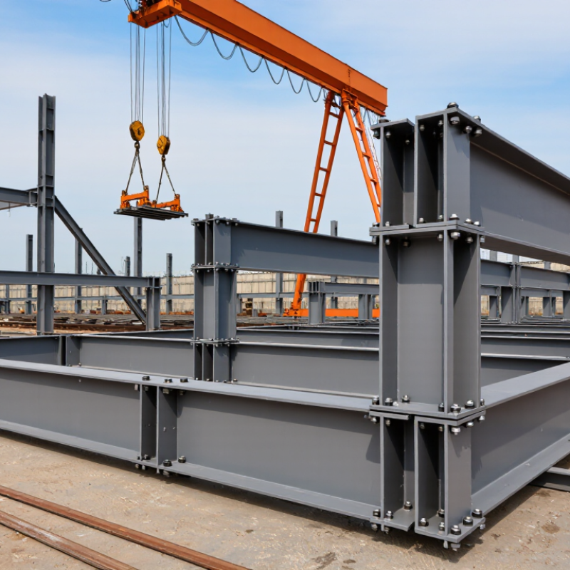
2026 Top Ways to Connect Steel Sections in Construction

Define Load Paths and Combinations: ASCE 7-22 Uses 1.2D + 1.6L

In steel construction, a connection is only as reliable as its defined load path. Under ASCE 7-22 strength design, the common gravity combination is 1.2D + 1.6L. Here, D represents dead load, while L represents occupancy or construction live load. Other combinations may govern when snow, wind, rain, or seismic effects apply.

A floor load should travel clearly from the slab to joists, beams, columns, and foundations. Each connection must transfer the forces expected at its location. Designers should check shear, tension, compression, flexure, bolt resistance, weld capacity, and local member failure. A beam-to-column connection may appear simple, yet eccentricity can increase bolt forces. Small geometry changes matter. Field measurements often reveal assumptions that drawings overlook.

Tips: Write the governing combination beside each design reaction. Confirm whether the project uses LRFD or ASD. Review load paths with the erection team before fabrication. Keep connection details consistent with the analysis model. A neat calculation can still contain a wrong assumption. I have found that the most useful review question is simple: “Where does this force go next?” Then check the answer against ASCE 7-22 and the applicable steel design provisions. Safety factors do not replace engineering judgment.

Select Bolts: ASTM F3125 Grades A325/A490 and RCSC Pretension

When connecting steel sections, bolt selection affects both strength and erection quality. ASTM F3125 covers high-strength structural bolts, including Grade A325 and Grade A490. A325 bolts suit many routine building connections. A490 bolts provide higher tensile strength for demanding designs. The engineer must confirm the specified grade, diameter, length, and washer arrangement.

RCSC pretensioned connections require more than simply tightening until the nut feels firm. Workers first bring the faying surfaces into firm contact, then apply the required pretension using an approved method. Common methods include calibrated wrench tightening, turn-of-nut, and direct-tension indicators. Field crews should mark completed bolts and record inspection results. Small details matter. A damaged thread can distort the reading. Poorly fitted washers may also reduce reliable clamping.

On site, I have seen crews focus on torque values while ignoring lubrication and bolt condition. That approach is risky because torque changes with friction. RCSC procedures therefore emphasize verification, not guesswork. A325 and A490 assemblies should remain matched with compatible nuts and washers, as specified by the project documents. A490 bolts also require careful corrosion-control review because common galvanizing practices may not be suitable. I would not treat every connection as routine. Weather, access, joint slip requirements, and erection sequence can change the correct installation method. Sometimes the drawing looks clear, but the field condition is not.

Design Welds: AWS D1.1, E70 Electrodes, and AISC 360 Limit States

Design Welds: AWS D1.1, E70 Electrodes, and AISC 360 Limit States

Connecting steel sections is not only about selecting an E70 electrode. The weld must transfer the required force through a controlled load path. AWS D1.1 governs welding procedures, workmanship, qualifications, and inspection for structural steel. An E70 electrode provides a nominal tensile strength of 70 ksi, but its actual suitability depends on the approved welding procedure, joint details, position, and service conditions.

AISC 360 requires engineers to check applicable limit states under LRFD or ASD. These checks may include weld-metal rupture, base-metal yielding, base-metal rupture, and connection shear. For a fillet weld, effective throat and effective length strongly influence capacity. A longer weld is not automatically better. Poor access, excessive heat, or an interrupted weld can reduce reliability. Field reviews often find drawings that show weld size clearly but leave termination details vague. That gap deserves attention.

Tips: Confirm the electrode classification before fabrication. Match the welding procedure to AWS D1.1 requirements. Check minimum weld size, effective length, and required inspection. Keep surfaces clean and dry. A neat weld is not automatically a safe weld. I still recheck load paths after revisions, because small connection changes can alter the governing limit state. Temperature, restraint, and fit-up also matter, even when the calculated capacity looks adequate.

Detail Moment Joints: AISC 358 Prequalified Connections for Seismic Demand

Moment joints are the backbone of steel frames resisting earthquake forces. AISC 358 prequalified connections help engineers select tested details for seismic demand. These connections have documented limits for geometry, materials, welding, and expected inelastic behavior.

In practice, detailing starts with the frame’s intended plastic hinge location. A reduced beam section may shift yielding away from the column face. Other prequalified options use bolted flange plates or welded flange details. The choice affects beam depth, erection access, inspection, and repair planning. Small details matter. Panel zones need adequate strength. Continuity plates must fit tightly and transfer concentrated forces. Demand-critical welds require qualified procedures and careful inspection.

AISC 358 does not replace engineering judgment. The designer must confirm that the selected connection matches the applicable moment-frame system and project conditions. Beam and column sizes, material grades, bolt installation, and protected zones all deserve direct review. Field crews often reveal problems that drawings miss, such as limited wrench clearance or inconsistent backing-bar removal. I have seen a connection appear complete while its inspection sequence remained unclear. That is a warning. Coordination between the engineer, fabricator, inspector, and erector should begin before shop drawings are issued. A signed calculation package is useful, but it cannot correct poor fit-up or rushed welding. Seismic reliability depends on the whole load path, not one impressive connection detail.

2026 Top Ways to Connect Steel Sections in Construction - Detail Moment Joints: AISC 358 Prequalified Connections for Seismic Demand
Connection Configuration Primary Joint Concept Typical Seismic Frame Use Force-Transfer Mechanism Key Detailing Features Principal Design Checks Relative Construction Considerations
Reduced Beam Section (RBS) Beam flanges are selectively reduced near the column face so that inelastic flexural yielding is concentrated in the beam away from the protected column region. Special Moment Frames Intermediate Moment Frames Beam flexure is transferred through welded beam-to-column flanges and a welded or otherwise detailed beam web connection. Controlled flange cuts, smooth transitions, adequate weld access, protected-zone limits, and continuity between the reduced section and the beam plastic hinge region. Required flexural strength at the reduced section, panel-zone shear, column-beam strength ratio, continuity plates, doubler plates, weld demand, and expected seismic rotation. Can reduce demand on the column connection, but requires accurate fabrication geometry and careful inspection of flange welds and access details.
Bolted Flange Plate (BFP) Beam flanges connect to plates attached to the column flange; the beam web is connected separately to transfer shear and stabilize the joint. Special Moment Frames Intermediate Moment Frames Moment is transferred primarily through bolted flange-plate tension and compression forces, while the web connection transfers shear and contributes to rotational stability. High-strength pretensioned bolts, adequate edge distances, plate thickness, bolt-group geometry, flange-plate welds, and a defined protected zone. Bolt bearing and slip considerations, plate yielding and rupture, block shear, column flange bending, panel-zone strength, weld strength, and beam plastic-hinge capacity. Moves much of the field work from welding to bolting; requires controlled bolt installation, fit-up, access, and inspection of flange plates and welds.
Bolted Unstiffened Extended End-Plate (BUEEP) A beam end plate extends beyond the beam flanges and is bolted to the column flange without separate end-plate stiffeners. Moment-Resisting Frames Seismic Applications Within Limits Flange tension and compression are transmitted through the extended end plate and bolt rows; the beam web and bolts transfer shear. End-plate thickness, bolt-row arrangement, column flange support, complete-joint-penetration beam flange welds where required, and clear protected-zone requirements. End-plate yielding, bolt tension and shear, prying action, column flange bending, beam and column local limit states, panel-zone shear, and connection rotation capacity. Factory-welded beam assemblies with field-bolted erection can improve site productivity; tolerances and bolt access are important.
Bolted Stiffened Extended End-Plate (BSEEP) An extended end plate uses transverse or triangular stiffeners to increase stiffness and strength at the beam-to-column interface. Special Moment Frames Higher Moment Demand Moment is transferred through tension and compression forces in the stiffened end plate and bolt rows, with the web connection carrying shear. End-plate stiffeners, bolt pretension, weld continuity, adequate column flange support, beam flange force transfer, and protected-zone coordination. Stiffener and weld strength, bolt tension and shear, prying action, column flange and web limit states, panel-zone demand, and required cyclic rotation. Provides greater connection capacity than an unstiffened plate in suitable cases, but has more parts, welds, and fit-up requirements.
Welded Unreinforced Flange—Welded Web (WUF-W) The beam flanges and web are connected directly to the column, with the beam flanges acting as the principal moment-transfer elements. Special Moment Frames Intermediate Moment Frames Beam flange forces are transferred through flange welds; the web connection transfers shear and part of the beam moment according to the qualified configuration. Qualified flange welding procedure, suitable weld access holes, backing and backing-removal requirements where applicable, continuity plates, and protected-zone detailing. Complete-joint-penetration weld strength, weld access-hole geometry, beam web connection, panel-zone shear, column local yielding, and cyclic ductility. Creates a clean architectural profile but can involve demanding field welding, strict environmental controls, and extensive nondestructive examination.
Welded Unreinforced Flange—Bolted Web (WUF-B) Beam flanges are welded to the column while the beam web is connected with high-strength bolts. Special Moment Frames Intermediate Moment Frames Flange welds transfer the principal tension and compression couple; the bolted web connection transfers shear and stabilizes the beam end. Qualified flange welds, bolted web angle or plate details, weld access holes, bolt installation, continuity plates, and protected-zone restrictions. Flange weld demand, bolt shear and bearing, web-connection strength, panel-zone shear, column flange bending, and expected connection rotation. Reduces field welding at the beam web while retaining welded flange force transfer; requires coordinated welding and bolting sequences.
Bolted Double Tee Connection Fabricated tee-shaped components connect the beam flanges and web to the column using bolted interfaces. Moment-Resisting Frames Modular Erection Bolted tee flanges transmit beam flange tension and compression; the web component transfers shear and contributes to moment resistance. Connection component geometry, pretensioned bolts, flange and web force paths, column attachment details, protected zones, and erection tolerances. Bolt-group strength, tee-stem and flange yielding, block shear, column flange and web limit states, panel-zone demand, and cyclic rotation capacity. Primarily field-bolted and potentially fast to erect; component tolerances, access for tightening, and shop fabrication quality are critical.
Reduced Beam Section with Bolted Components A reduced beam region is combined with bolted flange or end-plate components to promote beam hinging away from the column face. Special Moment Frames Seismic Retrofit Bolted components transfer the beam-end forces while the reduced section is proportioned to control the location of inelastic response. Specified reduction geometry, protected-zone limits, bolt installation, component fit-up, continuity plates, and compatibility between the reduced section and connection hardware. Reduced-section flexural strength, bolt and plate limit states, panel-zone shear, column-beam strength ratio, stability, and expected cyclic rotation. Can combine shop fabrication with field bolting; requires strict control of cut geometry and erection tolerances to preserve the intended plastic-hinge location.
General AISC 358 Qualification Requirements Prequalification applies only to connection configurations used within the stated material, member-size, geometry, welding, bolting, and seismic-system limits. SMF IMF Seismic Design The connection must provide the required strength and inelastic rotation while maintaining a reliable load path through the beam, column, panel zone, welds, bolts, and adjoining elements. Use the current standard’s listed limits, approved detailing provisions, qualified materials, specified weld procedures, inspection requirements, and protected-zone restrictions. Check required connection moment and shear, beam and column stability, panel-zone and continuity-plate requirements, welds, bolts, local buckling, and system-level strong-column/weak-beam behavior. Prequalification does not eliminate project-specific engineering, detailing, inspection, erection planning, or compliance with the governing building code and seismic provisions.
Design note: Connection names and characteristics are summarized for planning and comparison. Final selection must follow the requirements and limitations of the current AISC 358 edition, the applicable AISC seismic provisions, project specifications, and the governing building code. Prequalified status does not permit changes to critical geometry, materials, welding, bolting, or member limits without the required engineering qualification.

Verify Fabrication and Erection: AISC 303 Tolerances and NDT Levels

Steel sections connect through bolts, welds, or hybrid details, but connection quality depends on more than the design drawing. AISC 303 provides recognized practices for fabrication and erection, including dimensional control, fit-up, member position, and erection tolerances. The adopted edition and project specifications must be checked together. A tolerance that seems minor on paper can create visible flange gaps, difficult bolt installation, or unexpected force during erection.

AISC 303 does not establish one universal set of NDT levels. The contract documents should define the inspection method, examination extent, acceptance criteria, and responsible personnel. Visual inspection may apply broadly, while ultrasonic, magnetic-particle, liquid-penetrant, or radiographic testing may be required for selected welds. These requirements should align with the governing structural and welding specifications. Clear inspection hold points help prevent concealed defects from moving into the next phase.

Field verification should include calibrated measuring tools, documented observations, and prompt correction records. Check column plumbness, beam elevation, bolt-hole alignment, weld access, and temporary stability. Small gaps matter. A clean report can still miss a field problem if inspection stops at paperwork. In practice, teams sometimes measure after adjustment but forget the original condition. That weakens traceability. A better record shows the location, measured deviation, tolerance, repair decision, and final verification, with photographs where useful.

FAQS

How should high-strength structural bolts be selected?

Confirm the required grade, diameter, length, nut, and washer arrangement. Grade A325 suits many routine connections. Grade A490 serves higher-strength demands.

Does tightening a bolt until it feels firm achieve pretension?

No. Bring the connected surfaces into firm contact, then apply the specified pretension method. Feeling firm is not enough.

Which methods can crews use to apply bolt pretension?

Approved methods include calibrated wrench tightening, turn-of-nut tightening, and direct-tension indicators. Record the method used.

What site conditions can make bolt inspection unreliable?

Damaged threads, poor washer fit, lubrication, and changing friction can affect readings. Torque alone can mislead crews.

How should completed bolts be controlled during erection?

Mark completed bolts and record inspection results. Keep the records clear. A missed mark can cause repeated or incomplete work.

Why might an A490 connection need extra corrosion review?

Common galvanizing practices may not suit every A490 assembly. Check the project requirements before selecting corrosion protection.

Is selecting an E70 electrode enough for a safe structural weld?

No. The approved welding procedure must match the joint, position, materials, and service conditions. The electrode alone does not control safety.

What weld details affect connection capacity?

Check effective throat, effective length, minimum weld size, termination, and access. A longer weld is not automatically stronger.

Which failure conditions should engineers review in welded connections?

Review weld-metal rupture, base-metal yielding, base-metal rupture, and connection shear. The governing limit state may change after revisions.

What practical details should inspectors check before welding?

Keep surfaces clean and dry. Check fit-up, temperature, restraint, and required inspection. A neat weld can still be unsafe. I sometimes recheck the load path late, which is not ideal.

Conclusion

Understanding how to connect steel sections in construction begins with defining clear load paths and checking the required load combinations, including dead, live, wind, and seismic effects. Designers should select structural bolts with suitable strength grades and specify the required pretension when slip resistance or fatigue performance is important. Welded connections must be proportioned for applicable limit states, with electrode strength, weld size, access, and inspection requirements established during design.

Moment-resisting joints require careful detailing to transfer bending, shear, and axial forces while maintaining ductility under seismic demand. Connection details should be coordinated with member sizes, fabrication capabilities, erection procedures, and site tolerances. Before completion, the project team should verify bolt installation, weld quality, dimensional accuracy, and required nondestructive testing. A practical connection strategy therefore combines sound engineering calculations with precise drawings, realistic fabrication requirements, controlled erection, and thorough inspection.

Sophia

Sophia

Sophia is a dedicated marketing professional with an exceptional depth of knowledge about her company's products and services. With a keen understanding of market trends and customer needs, she crafts insightful blog posts that not only inform but also engage readers, enriching the company’s online......